WS2813 Signal Break-point Continuous Transmission LED
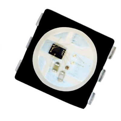
Refer to WS2813 LED, everyone may think of the ws2812b led,though they are all 3ch integrated digital rgb led (built-in ic led),but they have much different,firstly,ws2813 is dual-signal wire version in ws series leds,secondly the ws2813 have one more function:signal continuous transfer when there some break led,which can greatly improve the stability of the digital leds;the third one is tha the capacitance and resistance also package inside the led,this also will be much convenience for the pcb component designer,and reduce some SMT ,and save many space for other element.

General description
WS2813 LED is an intelligent control LED light source that the control circuit and RGB chip are integrated in a package
of 5050 components. Its internal include intelligent digital port data latch and signal reshaping amplification drive circuit.
Also include a precision internal oscillator and a 12V voltage programmable constant current control part,
which achieves highly consistent color effect.
The data transfer protocol use single NZR communication mode. After the pixel power-on reset, the DIN port receive
data from controller, the first pixel collect initial 24bit data then sent to the internal data latch, the other data which
reshaping by the internal signal reshaping amplification circuit sent to the next cascade pixel through the DO port. After
transmission for each pixel, the signal to reduce 24bit. Every pixel adopts auto-reshaping transmit technology, making
the pixel cascade numbers are not limited to the signal transmission, only relate to the speed of signal transmission.
The BIN receives the data signal, and then compare the data with the DIN side after phagocytosis of 24bit data, if DIN
do NOT receive the signal, then switching to BIN for receiving the input signal, which ensure that any the IC's damage
does not affect the signal cascade transmission and make the BIN in state of receiving signal until restart after power-off.
Refresh Frequency updates to 2KHz, Low Frame Frequency and no Flicker appear in HD Video Camera.
250us or more of reset time, it won’t cause wrong reset while interruption, it supports the lower frequency and
inexpensive MCU.
There’re in a choice of 18mA or 5mA current version, and also in a choice of high brightness or cost-effective version.
WS2813 LED is an intelligent control LED light source that the control circuit and RGB chip are integrated in a package
of 5050 components. Its internal include intelligent digital port data latch and signal reshaping amplification drive circuit.
Also include a precision internal oscillator and a 12V voltage programmable constant current control part,
which achieves highly consistent color effect.
The data transfer protocol use single NZR communication mode. After the pixel power-on reset, the DIN port receive
data from controller, the first pixel collect initial 24bit data then sent to the internal data latch, the other data which
reshaping by the internal signal reshaping amplification circuit sent to the next cascade pixel through the DO port. After
transmission for each pixel, the signal to reduce 24bit. Every pixel adopts auto-reshaping transmit technology, making
the pixel cascade numbers are not limited to the signal transmission, only relate to the speed of signal transmission.
The BIN receives the data signal, and then compare the data with the DIN side after phagocytosis of 24bit data, if DIN
do NOT receive the signal, then switching to BIN for receiving the input signal, which ensure that any the IC's damage
does not affect the signal cascade transmission and make the BIN in state of receiving signal until restart after power-off.
Refresh Frequency updates to 2KHz, Low Frame Frequency and no Flicker appear in HD Video Camera.
250us or more of reset time, it won’t cause wrong reset while interruption, it supports the lower frequency and
inexpensive MCU.
There’re in a choice of 18mA or 5mA current version, and also in a choice of high brightness or cost-effective version.
That is to say, WS2813 is provided with four versions
Features and Benefits
The control circuit and the LED share the only power source.
The control circuit and RGB chip are integrated in a 5050 components, to form an external control pixel.
Using the built-in signal reshaping circuit to achieve the signal waveform shaping, and no distortion of waveform of
signal takes place.
Built-in power-on reset and brown-out reset circuits.
The gray levels of each pixel are of 256 levels, which achieves “256*256*256=16777216” full-color display, and
the refresh frequency reaches to 2KHz/s.
Serial cascade interface, data receiving and decoding depend on just one signal line.
Dual-signal wires version, signal break-point continuous transmission.
Any two point the distance more than 3m transmission signal without any increase circuit.
When the refresh rate is 30fps, cascade numbers are far more than 1024 points.
Data transmitting at speeds of up to 800Kbps.
Good color consistency reliability, high cost-effective.
Applications
Guardrail tube series, point light display series, flexible/rigid strips series, module series applications.
Lighting stage costumes, innovative gadgets or any other electronic products.
Datasheet of WS2813 LED
The control circuit and the LED share the only power source.
The control circuit and RGB chip are integrated in a 5050 components, to form an external control pixel.
Using the built-in signal reshaping circuit to achieve the signal waveform shaping, and no distortion of waveform of
signal takes place.
Built-in power-on reset and brown-out reset circuits.
The gray levels of each pixel are of 256 levels, which achieves “256*256*256=16777216” full-color display, and
the refresh frequency reaches to 2KHz/s.
Serial cascade interface, data receiving and decoding depend on just one signal line.
Dual-signal wires version, signal break-point continuous transmission.
Any two point the distance more than 3m transmission signal without any increase circuit.
When the refresh rate is 30fps, cascade numbers are far more than 1024 points.
Data transmitting at speeds of up to 800Kbps.
Good color consistency reliability, high cost-effective.
Applications
Guardrail tube series, point light display series, flexible/rigid strips series, module series applications.
Lighting stage costumes, innovative gadgets or any other electronic products.
Datasheet of WS2813 LED


